Series Compensation: The Under-Appreciated Transmission Improvement
Everyone wants better line and system performance
The usefulness of a transmission line is limited by its thermal rating (ampacity), and its series impedance.
The ampacity can be increased by
- installing larger conductor;
- installing multiple conductors per phase (“bundled conductors”);
- installing conductor capable of withstanding higher operating temperatures.
From this list it is seen that increasing the ampacity is primarily a mechanical undertaking. Not much here for us electrical engineers.
The series impedance, which consists of resistance and inductive reactance, limits line performance in several important ways:
- The resistance causes real power (I2R) losses, and IR voltage drop.
- The inductive reactance causes reactive (I2X) losses and IX voltage drop.
- The inductive reactance limits the amount of power that can be transferred:
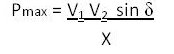
Since “X” is in the denominator, reducing the X increases the Pmax. Alternatively, reducing the X reduces the amount of voltage phase angle displacement required to achieve a certain power transfer. This tends to help improve the power system dynamic stability.
The only good thing about series line impedance is that it limits fault current availability. Normally, fault current levels are not a problem, and it’s desirable to lower both the resistance and inductive reactance if possible.
Reducing the resistance is done by the methods #1 and #2 above used for increasing ampacity. There are no electrical “tricks” for reducing resistance.
Reducing the inductive reactance can be done by either installing bundled conductors (25-30% reduction) or by series compensation. Series compensation is a wonderful electrical “trick”.
How it’s done
Series compensation involves inserting a capacitor bank in series with each of the three phases of the transmission line. The ohmic value of the capacitor is chosen to compensate for a certain percentage of the line’s inductive reactance. Typically, 35% to 80% compensation is applied. Here in the U.S, series compensation became popular in the Western states, where lines are often very long. Many installations were made at 345 and 500 kV starting in the mid 1960s.
Series compensation is most effective on the higher-voltage transmission lines (230 kV and above) because they have relatively high ratios of series X to series R; typically 7 to 20 or so. For example, the typical 345 kV line has an X/R ratio of about 10 and a 500 kV line has an X/R of about 18.
Series capacitors need to be protected against fault currents because the high through currents (as during line faults) will cause abnormally-high voltage (IX) to develop across the capacitor. The through-fault protection nowadays is achieved with banks of Metal-Oxide Varistor (MOV) and sometimes also with an old technology known as a Triggered Air Gap (TAG). For long-duration faults, the bank’s bypass breaker can also be brought into play.
What makes series compensation desirable?
Series capacitors are wonderful devices because by reducing the line’s apparent series inductance
- dynamic stability is enhanced;
- voltage profiles are improved;
- net reactive power consumption is reduced (the line’s I2X consumption is offset by the capacitor’s I2X reactive power production)
- system voltage stability is improved (reactive output does not decline with declines in system bus voltages)
- load-sharing among parallel lines can be adjusted to compensate for differing lengths, or to make the lines load in proportion to their thermal ratings.
Normally, the series capacitors are left in-circuit at all times, though they can be switched out if desired.
How do series capacitors compare to the more common shunt capacitors?
- Shunt capacitors must be switched “on” and “off” in response to bus voltage changes
- Shunt capacitors’ reactive output is proportional to the square of the bus voltage (V2B); this is undesirable, as a voltage decline causes a decline in capacitor VAR output, at precisely the moment that VARS are most needed. This is a voltage stability concern, as it gives positive feedback to any voltage disturbance.
- Shunt capacitors do not change the line’s series impedance, so no reduction in voltage phase angle displacement is obtained. Dynamic stability is not improved.
- Series capacitors’ VAR output (I2X) is determined by line loading, so their VAR output automatically increases (instantaneously) with increased line VAR consumption. No switching is required.
Drawbacks are few
Whenever we tinker with system impedances, new resonant combinations are possible. Sub-Synchronous Resonance (SSR) is a condition where one of the power system’s resonant frequencies corresponds to the complement (60-f) of one of the mechanical resonance modes of a turbine-generator. Sustained SSR conditions can result in fracture of the machine shaft; this causes consternation among the mechanical engineers. SSR conditions can also be excited in certain non-synchronous machines, as in some wind farms. It should be noted that generators’ SSR exposure is not only a “series capacitor” phenomenon. SSR conditions can be created or excited by other equipment, such as DC line converter stations, and actions such as repetitive reclosing into faults.
Fortunately, SSR conditions related to series compensation tend to arise only when a generator is connected radially into a series-compensated line; this is an unusual condition that rarely occurs. Today we simply avoid such configurations whenever possible. SSR protection relays are available, and analytical techniques have been developed during the past 4 decades that allow for identification of potentially-problematic operation conditions and evaluation of SSR countermeasures.
In cases of particular concern, special counter-measures can be implemented, such as subsynchronous filters to block low-frequency currents, and special supplemental controls on thyristor-controlled series capacitor banks.
Summary
Series capacitors are an important and valuable technique for improving the electrical performance of a line, and the power system of which it is a part. The reduction achieved in net series line impedance improves power system performance from the standpoint of both dynamic stability and voltage stability. Unlike shunt capacitors, series capacitors do not ordinarily need to be switched in or out in response to changes in power system conditions, and their reactive output is not dependent on bus voltage.
R Gonzalez, PE