Extend the valve control flow range with staged valves
A single valve may not have the resolution needed to adequately control the process.
Another example is while dealing with large flows requiring precise control over the whole flow range. Providing a single valve with the required Cv (effective valve flow coefficient) characteristics may be extremely expensive while two (or more) valves are able to achieve the same Cv occur at a more attractive price. A typical example of this would be a 1000 psi or 2500 psi ASME B31.1 class valve passing 6 million pounds of water per hour.
Although this arrangement would seem to be straight-forward, the control engineer has the issue to stage the control signal between two (or more) valves. At the point of “overlap” between two valves he may experience a discontinuity in the change in the Cv factor. If the second valve in the series fails to respond at the appropriate time, the process will experience a “dead band”. If the second valve in the series responds too soon, the process will experience a discontinuity with an excessive process gain. In each of these cases the control of the process will suffer at this overlap.
In the “old days” when multiple valves were controlled by a single analog signal (either pneumatic or electronic current) the Instrument Technician had the task to properly adjust the valve positioners so there would be a uniform transition between the two valves. Typically these were mechanical/pneumatic devices and eventually the calibration would drift thus causing the process to again suffer from a discontinuity at the overlap point.
Along come the new electronic systems with separate signals to the each of the staged valves. This obviously will solve our problems – won’t it? These new electronic (and digital) systems have lots of new flexibility. Unfortunately the fundamental problems with those nasty mechanical devices in the field (valves and positioners) still have the same problems – the valves do not necessarily move exactly when you desire.
The following graph shows the ideal approach that the instrument technician is trying to achieve:
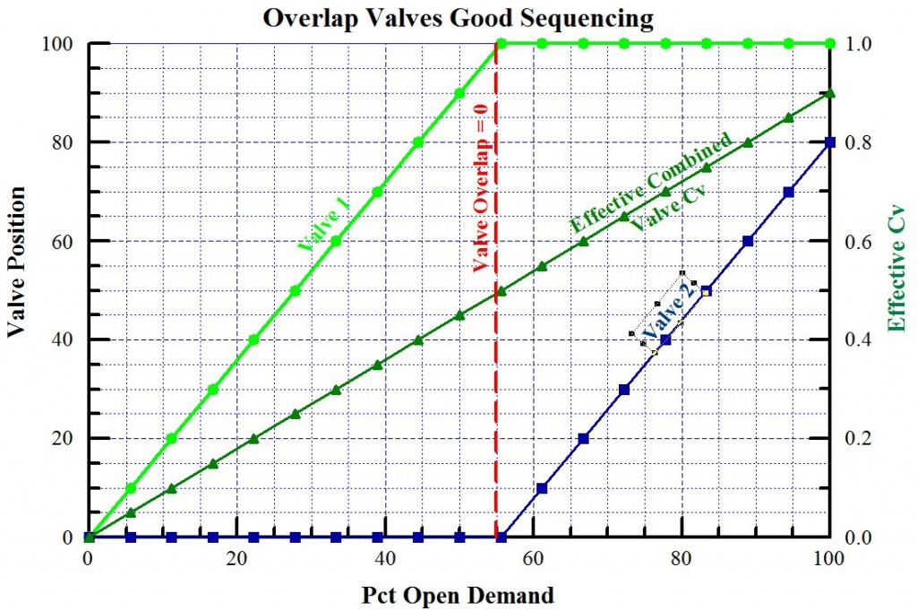
In this case we see that as the first valve ends its contribution to the flow, the second valve begins contributing to the flow leaving no discontinuity in the effective valve Cv. There is no observable overlap or dead band in the transition.
Even if the valve set was placed in service meeting this ideal sequencing, the valve calibration may drift over time or experience “sticktion” (sticking and friction) and create a dead band discontinuity.
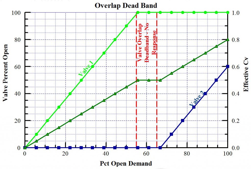
In this case the second valve does not respond and an area of zero response from the effective Cv occurs. Attempting to tune a system across this range may result in unstable response in the other active valve response areas.
If the second valve drifts lower and responds too quickly then a change in gain occurs in this overlap. The control may be unstable in this overlap area. If the system is tuned to accommodate this mechanical gain, it may be sluggish in the areas outside this overlap area.
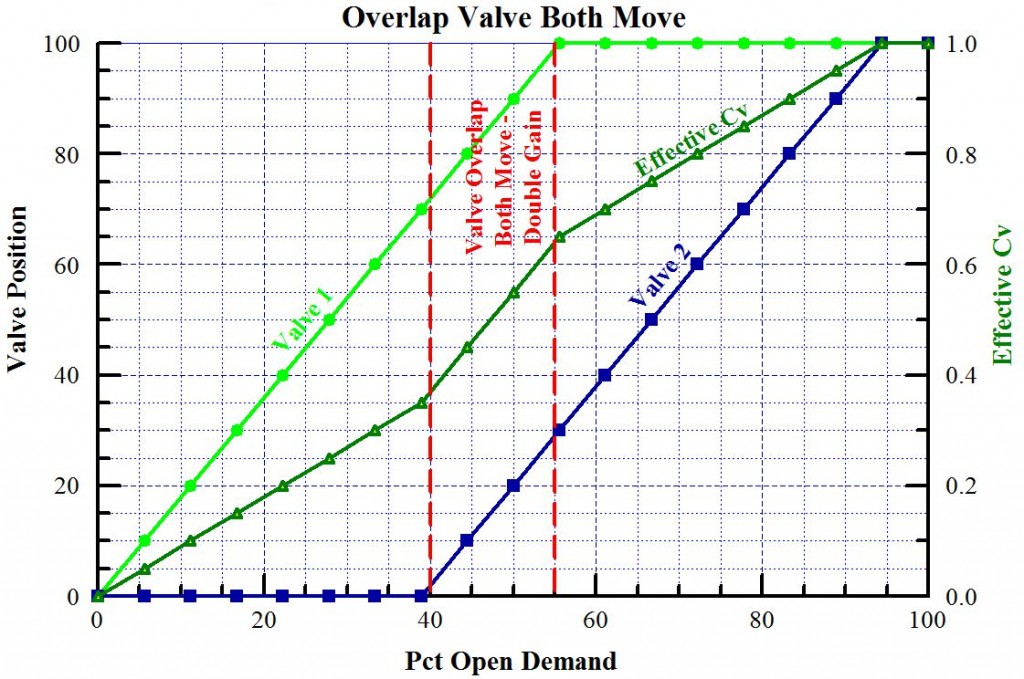
In this case we can see that the response of the system in this overlap area has doubled. When either of these undesirable overlaps occur (dead band or overlap) the valve set should be re-calibrated.
In general we tend to see the problems of valve movement occur at or near the closed position of the valve. As a method to minimize this discontinuity we can use the new digital control systems to manipulate each valve separately. We can then “ease” the second valve from the closed seat and ease the valve open slowly. This will occur in a designed overlap where the second valve is commanded to open at a much slower rate than the first valve. In this overlap area we may extend the “cracking” point over a 10 or 15 percent open demand range. This also works using valves in a high turn down application. The example below uses two valves that provide a very high turn down that minimizes the discontinuities at the valve overlap range.
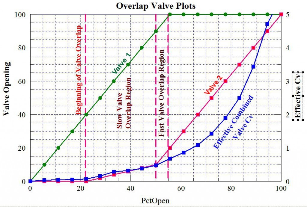
This arrangement above has a very slow response over the first 50 percent of the valve demand range to accommodate the flow/thermodynamic characteristics of the process. The overlap allows a continuous change in Cv and minimizes the valve “sticktion” that can occur at the opening of the second valve. Two overlap regions are designed. The “Slow Valve Overlap Region” cracks the second valve from the seat and opens it uniformly over a small amount over this 25% region. The “Fast Valve Overlap Region” moves the second valve faster to ensure a uniform change in the effective Cv of the valve set.
The next submittal will address “Participation of Multiple elements”. Sometimes a particular process may require several items operating in parallel with each other but each item is controlled separately by the control system.