Time-current curves (TCCs) graphically depict the interrupting time curve of a protective device based on the available fault current on a log-log-based graph. The curves rely on the physical characteristics and construction of the protective device, as well as the selected settings for applicable devices.
Time-current curves are essential to electrical safety because they allow the engineer to graphically represent and interpret the coordination of protective devices in electrical systems. Properly coordinated systems generally result in lower arc flash hazards, lower chances of nuisance tripping, and isolated, shorter outages in the event of a fault.
Here, we will aim to help project managers and engineers understand how to interpret TCCs and the importance of proper protective device coordination.
The Basics of TCCs
Time-current curves depict the time required for protective devices (i.e., circuit breakers) to operate at a given fault current level. This information is typically plotted with time (seconds) vs. current (amperes).
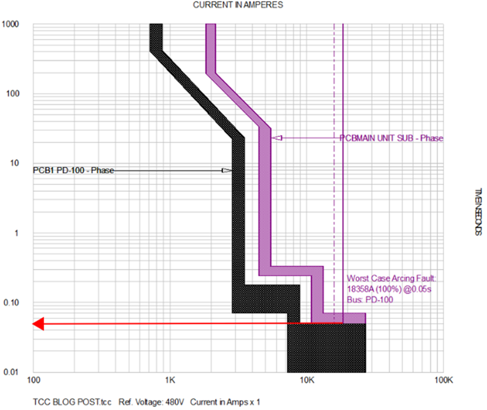
Overcurrent protective devices limit current and disconnect short circuits. To determine how long a breaker will take to trip, use the available fault current at the bottom of the graph, draw a vertical line to the point where it intersects the time-current curve, and follow the horizontal line to the left side of the graph to find the trip time.
Reading and Interpreting TCCs
Time-current curves have several standard components that should be considered. The components are listed and shown on the graphic below.
- Long-Time Pickup – Overload trip element. Allows for low-fault currents to clear without tripping the breaker, in addition to temporary overload conditions.
- Long-Time Delay – Overload trip element delay.
- Short-Time Pickup – Short trip element. Allows for moderate-fault currents to clear without tripping the breaker. Useful for motor-starting or transformer inrush currents.
- Short-Time Delay – Short trip element delay.
- Instantaneous Pickup – Instantaneous trip element. Trips on high-fault currents with no intentional delay. This function protects electrical equipment from damage and will keep arc flash hazards lower.
- Ground Fault Pickup – Ground trip element.
- Ground Fault Delay – Ground trip delay element.
- I2t – Inverse time curve (ON/IN or OFF/OUT).
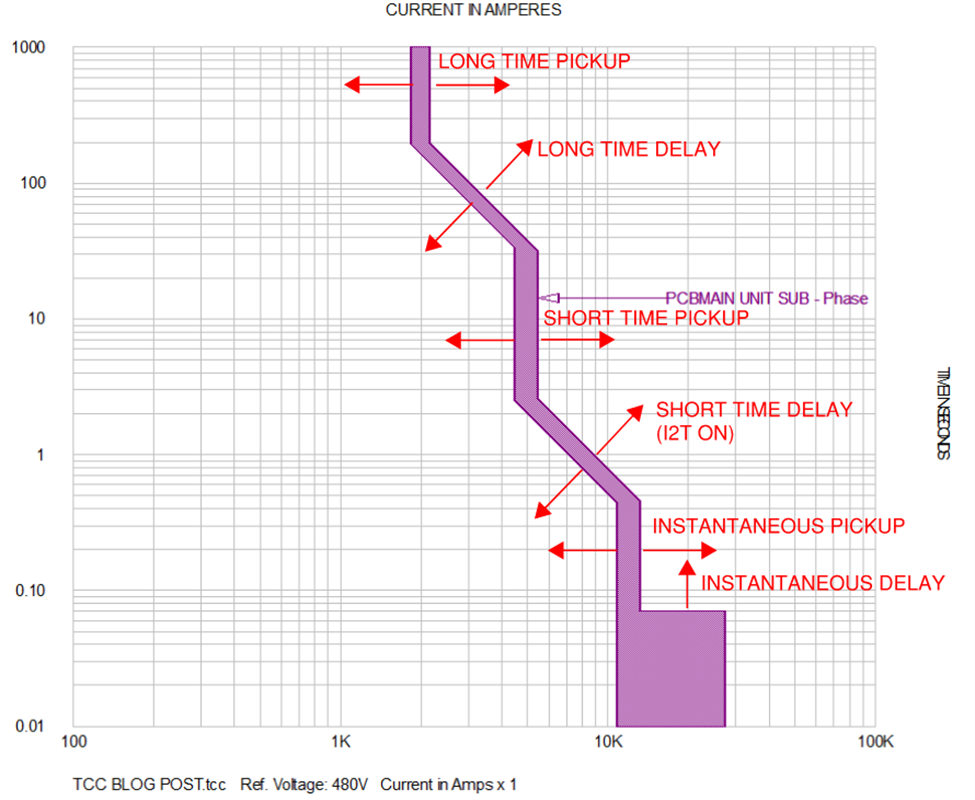
In the image above, the TCC curve is displayed with a band, shown in purple, that can be attributed to the breaker trip unit’s physical characteristics. Typically, this band is + 20% of the setpoint. It is important to note that most circuit breaker and fuse TCC curves will be shown with a band, whereas relays will not be shown with a band. For relays, the processing time, breaker opening time, CT accuracy, and relay accuracy need to be accounted for when selecting the appropriate time interval between protective devices.
- The minimum clearing time is the portion of the band closest to the y-axis and represents the time the breaker senses the fault and the breaker will begin to open.
- The maximum clearing time is the portion of the band furthest from the y-axis and represents the maximum time the breaker will open.
- There are several conditions that can cause variations in a protective device’s performance, including maintenance condition, age, and the available fault current.
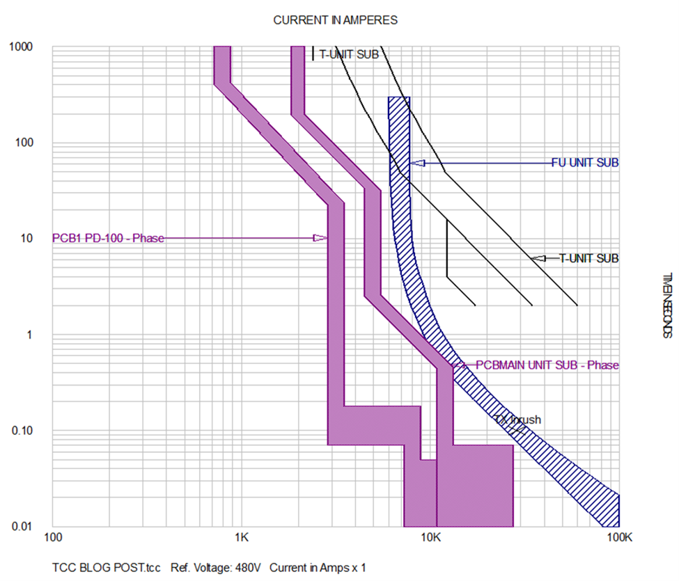
There are many factors which play a role in protective device coordination. In general, protective devices should be coordinated to prevent nuisance tripping. If devices cannot be fully coordinated, engineering judgement must be used to determine settings that will result in the least disruption to the facility in the event a fault occurs. Also, if a protective device is feeding equipment with large inrush currents (such as motors, transformers, etc.), the settings should be set high enough to prevent tripping when the equipment is energized.
Downstream protective devices (i.e., a motor overload) should be set to trip before upstream devices (i.e., the MCC main breaker). This will ensure the system is set up to isolate energy from one motor instead of your entire production line.
TCC Curves and Circuit Protection
TCC curves can be leveraged to help select the appropriate overcurrent protective devices that will fall within your budget, satisfy your power system requirements, and that are properly rated for the available fault current.
The time-current curve of the protective device itself can also be analyzed to help determine coordination and arc flash hazards. To get there, simply iterate until the required coordination and level of hazard reduction are fulfilled.
Advantages and Disadvantages of Circuit Protection Devices
Different types of circuit protection devices, namely fuses, circuit breakers, and relays, all have their own advantages and disadvantages to consider.
Fuses are cost-effective, simple, and fast-acting, in addition to delivering standalone operation. They have limited maintenance requirements but also lack TCC adjustability. Fuses also need to be replaced after the fault has been cleared.
Circuit breakers are more costly and complex than fuses, but are also fast-acting and capable of enabling standalone operation. They may provide some TCC adjustability, must be reset after the fault has been cleared, and require maintenance to ensure reliability.
Relays are the most costly option of the three, primarily because they require separate sensor inputs and fault interrupters/breakers. Like circuit breakers, relays are also complex and fast-acting but are the best option for TCC adjustability. They must also be reset, and the fault interrupter reclosed after the fault has been cleared. Relays require routine maintenance to ensure reliability.
Ultimately, selecting the appropriate device for your specific application based on TCC curves comes down to two key factors: comprehensive understanding of protective device coordination and firsthand experience. For personalized guidance in selecting the right device for you, contact the team of experts at Excel Engineering.
About Excel Engineering
Since 1990, Excel Engineering has helped industrial manufacturing, utility, and life sciences clients bolster their workforces and processes in a way that saves on labor costs, improves efficiency, and that ultimately produces a better bottom line. From electrical design and industrial automation to power systems studies and construction management, we have everything you need under one roof, and are just the right size to deliver on it day in and day out.