Pumps will perform as designed and last a long time as long as we respect their limitations and treat them well. There are several parameters that the mechanical or process engineer and control designer need to understand and respect. These parameters include:
1. NPSHRequired and NPSHAvailable
2. Minimum Stable Flow
3. Pump Curves
4. Best Efficiency Point
5. System Flow Curve (Provided by system designer)
This data is provided by the pump manufacturer because it is important for the long-term operation of the pumping equipment. Now it is up to the control designer to be sure that each of these parameters is respected for the protection of the pumping equipment.
What is NPSH for pumps?
In addition the pump suction piping should minimize the pressure losses due to flow to maximize the NPSH available (NPSHa) to the pump. The system designer and control designer can maintain this value by assuring that the pressure or level in the upstream tank or source is maintained above a minimum level in the supplying tank or minimum static pressure. Also any valves selected for pump isolation should provide a minimum pressure loss by allowing a full bore opening while in the full open position. Two valves that meet this duty are gate valves or full bore ball valves. (3/4 ball valves do not provide a full pipe opening and can restrict flow/increase pressure loss – thus reducing NPSHa).
Once the upstream level and pressure are established and an appropriate control approach is determined, we can attack the next parameter.
Minimum Stable Flow
Pumps cannot operate in a deadheaded condition for very long. All of the power produced by the motor will be turned into heat within the pump casing. Forces acting on the impeller and shaft within the pump will be severely imbalanced. Leakage flow from the discharge to the inlet of the impeller adjacent to the pump casing can flash and increase erosion of the wear rings or close tolerance parts.
Manufacturers will provide a value of flow through the pump that will prevent the pump from overheating and reduce the imbalanced forces to a level that can be supported by the shaft and bearings supplied with that pump. This value is called the “minimum stable flow” or “minimum flow”.
The system designer and control designer should be aware that even when the pump is operated at the Minimum Stable Flow, this will reduce the life of the pump. However, this will still be within the capabilities of the pump. If multiple pumps are running in parallel in the process, consideration should be given to shut-down a pump running at minimum and increasing the load on the remaining pumps.
Additional system design considerations should be made to provide a recirculation for the pump to allow the pump to be continuously operated above the minimum stable flow. The control philosophy should be developed to maintain flow through the pump above the minimum flow with additional margin through the recirculation line as needed.
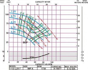
Pump Curves: Best Efficiency Point
The manufacturer will provide a curve specific to the pump or a series of curves of all the standard impellers that fit within that pump casing. These curves provide the relationship between the head developed by that casing/impeller combination with respect to the flow through the pump. These curves will also identify the best efficiency point (BEP) for the best combination of head-flow.
System Flow Curve
The process engineer would have determined the flow path, piping sizing, intermediate components and produced a system flow curve. This curve would reflect the flow versus loss of head within the flow path. Presumably the process engineer would have selected a pump and impeller size that best matched the anticipated flow. The control engineer should double-check that there is sufficient margin in the pump to support degradation of the pump or accommodate fouling of the flow path. The control engineer should then check the flow characteristics of the control valve to help linearize the response of the control valve. If there is a large change in the system gain with respect to valve position, the control designer should recommend an appropriate valve position-flow characteristic.
Now that the pump, flow design and pump protections are determined, we should walk through the selection of an appropriate valve trim for the system.
Next time:
Control the flow – select an appropriate valve trim